 What follows is a very instructive article on a PID temperature loop control example by Wayne Salo over at Excel Engineering in the St. Paul, MN area. It shows how temperature control can start as a fairly simple system,
but over time (and as learning takes place) the control can get fairly complex as the desire for tighter control increases as was the case in this project.
The project was posted as 4 separate Blog articles over a period of time starting with http://74.95.67.199/controls/2013/03/18/hot-water-project-phase-1/. I’m republishing these articles here so the reader can see the progression of solutions offered, all to achieve increasing levels of control needed for what turned out to be a tightly controlled application using process knowledge, feed forward, and a cascaded PID control.
_______________________________________________________________
Hot water project – Phase 1
One of the more common projects is to heat water (or some other liquid) from a random cold temperature to a desired working temperature. The inevitable discussion occurs with your boss or the customer regarding the usual items – schedule, scope and costs.
If you are lucky, the customer has properly identified the scope of the project. He has adequately determined the variation of the process input temperatures and flow, variations in the heating media, identified the economic value of maintaining a specific temperature or incremental losses due to off-spec temperatures and identified potential future uses and changes for the output of this process. He would also have properly identified reasonable capital costs and provided adequate lead time for this engineering process.
Dream on! The majority of projects seem to be “We are tight on the schedule, we needed the control design done yesterday”. “Oh, by the way, this was an oversight so we don’t have any budget identified for the control equipment, so the cheaper the better”. “You may want to talk with the Project Scheduler so we can keep your costs in tow”. “All of the information you need is in the plant documentation files”. “The Process Engineer has already bought all of the control elements so you may want to talk with him”.
In subsequent discussions with the Project Manager and Process Engineer you find that a closed tube and shell heater (a heater in which the heating and process fluids do not mix) has been ordered. The heating media will be steam and condensate drips will be removed from the shell by pump. The process fluid is water and the final users/process will control the water throughput. The heating steam admission valve and process water flow valve have been procured. Both valves were purchased with trim linearized within the process piping. The downstream process that uses the heated water is proprietary and if they tell us about the process they will likely have to shoot us.
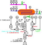
The system as ordered appears relatively simple. Following the instructions as requested by the customer, a simple (cheap) control system was created.  The temperature of the water exiting the heater was measured, compared with an Operator adjustable setpoint and the Heater Steam Supply Valve is manipulated to control the water outlet temperature.
The system is commissioned and tuned and it appears the customer is initially satisfied that the control system is working as requested. All is good and it is time for a beer.
Six months later the customer calls and is now unhappy with the system performance. They have performed testing and some areas of opportunities were identified.
Next time – Hot water project – Phase 2
Hot water project – Phase 2
As we noted in the last blog, the customer has told you he is unhappy with the temperature control of the process water. After signing a telephone book of nondisclosure agreements the customer has offered additional information regarding his process.
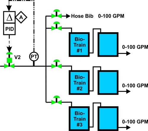
During the past months of operation they have been able to characterize the efficiency of the process in which the steam is being used. They inform you that the water is being used to supply a bioreactor with process water. In addition they have provided you with charts that indicate the process efficiency versus the water temperature presented to the bioreactors and Piping and Instrumentation Diagrams (P&ID).
We also note that the customer has identified that the best operating point is at 112 degF and the production efficiency falls off significantly both above and below this target temperature. The enzyme reactants are expensive and it is in their interest to minimize the waste and costs by more accurately controlling the temperature.
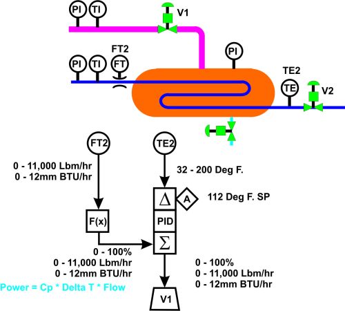
Also it was noted that the usage by the reactors was inconsistent and changes in the flows were causing a sluggish response in the final temperature. When one of the reactor trains is placed into service or removed in service, the flows would dramatically change and the spikes in temperature would waste reactants. They needed a mechanism to properly respond to these changes in demand. They also remind us that their operational budget does not necessarily have lots of money available for any changes – so the cheaper the better. So we decided to track the position of V2 (the water flow control valve) and feed forward that signal to the steam valve V1 to minimize anticipate the demands for the steam heating requirements. As a result the following control scheme was provided.
Since the process engineer had linearized the valves we could easily relate the water flow valve position to an appropriate position demand for the steam supply valve. The system was configured, scaled and tuned, the customer is happy with the change – time for another beer.
We receive a phone call approximately 3 months later and the customer informs us that the control performs better – but – there is a problem when the water inlet pressure to the heater changes and the water valve position does not accurately represent the flow through the system.
They ask for a change to correct the problem.
The next step in the process –
Next time – Hot water project – Phase 3
Hot water project – Phase 3
As we noted in the last blog, the customer noted that the water pressure varied and the water control valve position did not necessarily represent the flow through the heater. The customer has indicated that they would be able to release some additional funds for process instrumentation.
At this time a flow measurement of the incoming water was added and the control configuration modified and rescaled to respond to actual water flow.
A flow transmitter, FT2, was added and used to replace the valve position feed forward. Since we know the relationship between flow and heating demand we were able to easily rescale the feed forward to steam valve position demand change.
Modifications were made to the configuration, blocks rescaled and system retuned. Customer exercised changes in the upstream water pressure and was again happy with the new configuration results.
Again we received another phone call approximately 3 months later. The customer indicates that when they switch from city water at 70 degrees to well water at 50 degrees, the system takes too long to respond to these changes. They asked if we could help them with the response of the system.
At this time we proposed that we actually measure the incoming water temperature and anticipate the demand to the steam valve. After the customer agrees to the additional costs of the instrumentation, we provide a new solution.
With this modification we no longer depend on the design differential temperature demand for the feed forward, we actually measure the flow and needed increase in water temperature. From these we can directly calculate the power demand and feed forward this scaled demand to the steam valve. Again the system is reconfigured, rescaled and tuned. And again the customer is happy with the changes made to the system. And again we are ready for beer time.
The customer calls back approximately 3 months later and indicates that there are still opportunities to minimize temperature deviations. They have noted that when the other process steam demand changes, the inlet steam pressure changes and they do not necessarily get the steam flow desired into the heater.
Next time – let’s get the steam under control.
Hot water project – Phase 4
Hot water project – Phase 4
As we noted in the last blog, the customer noted that the steam pressure varied and the steam control valve position did not necessarily represent the steam flow to the heater. Let’s get the steam under control.
We tell the customer that the addition of instrumentation to the steam lines will cost more than the previous instruments we have already added. They indicate that even small reductions in the loss of reactants would cover any of the costs of new instrumentation.
We inform the customer that we will add a temperature compensated steam flow meter and reconfigure the controls to accommodate the new instrumentation. The following is the new control arrangement.
You will note that we have now moved from a simple feed forward control to a feed forward – cascade control system. The reason for the cascade is we now are actually controlling the steam flow by manipulating the steam valve. The “inner loop” (steam flow) will be tuned first and then the “outer loop” (steam flow demand) will be tuned. The feed forward is now rescaled from valve position to steam flow demand. And again we implement and tune the new configuration. The customer is happy with the new and smaller error band of the water temperature.
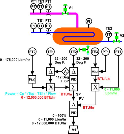
The customer calls again in several months and indicates that they have related some small temperature differences in the water to incoming steam temperature. Reducing these temperatures could again reduce the loss of reagent in the bioreactors. We have one final change and inform the customer that it will not require the addition of any instrumentation – only some engineering and reconfiguration of the control arrangement. The following is what was proposed.
In this case we add an enthalpy calculation to the steam. Some manufacturers have this block built-in to their algorithm set but in most cases this calculation is performed using multiple blocks. Using the steam pressure and temperature we can calculate the energy contained within the steam (enthalpy). Since we also are measuring the actual steam flow, we can now directly control the energy entering the heater due to the steam. This is a full model of the process. We measure and calculate the energy demand required by the water and directly control the heating energy provided by the steam.
The control configuration is rescaled such the inner loop controls the total BTU/Hr provided by the steam while the feed forward and outer loop is rescaled to BTU/Hr.
The result of this set of blogs on the heater project is a take-away with several lessons.
- . – Many of the control projects begin as an afterthought.
o Budgeting, scope and schedule need proper attention
o Major needs are not included in base design
o Operational efficiencies may not be appreciated
- . – Skill set of the Process Engineer may not include adequate control skills
o The Process Engineer may understand process very well but not all of the associated interactions needed for the application and design of the needed control arrangement
- . – Management and operations live with the limitations of the control process. They do not want to spend the money or shut down production for any enhancements. The revenue they may lose due to the maintenance shutdown is a deterrent to any appropriate upgrades to the system.
o Most control projects do not evolve beyond first simple regulatory control implementation (Process Measurement -> PID controller -> Manipulated device).
o Extensive efforts are made to adapt and modify the tuning parameters with respect to the existing measured parameters but no additional efforts are made to add instrumentation and properly enhance the model of the application.
- . – Spending the time and effort at the beginning of the project to determine scope of instrumentation and control required for the long-term best profit over the life of the system will pay off large in the long run. Establishing a proper design and cash-flow will identify the extent of modeling that will be cost effective.
_______________________________________________________________
For Waynes other articles on Process Control see http://74.95.67.199/controls/.
_______________________________________________________________
| Created: 11/1/2013 10:55 am CST; for Publishing on 11/12/2013 at 5:00 am CST


Leave a comment