Posted by: Harold Ennulat | October 10, 2016

Fail Safe Design

failsafegraphic2

Fail Safe Considerations in Controls – Introduction

When selecting components and doing a control system design, the failure state(s) of the various devices and the controls need to be considered.

Once the final selections have been made, another review of the failure modes of the various devices and the design should again be made prior to making any purchases (or procurements).

The most common reason I still encounter for using devices or designs that do not fail safe, is simply that failure of the device or design is not considered.

What is Fail Safety?

In looking up the definition of what constitutes something that is “fail-safe” this is the definition used in this article and is adapted from http://www.audioenglish.org/dictionary/fail-safe.htm.

FAIL-SAFE (noun) –   The noun FAIL-SAFE has 1 sense:

1. a mechanism (or system) capable of returning to a safe state in case there is a failure or malfunction.

To this definition I would add that in practice the engineer is looking at the most likely failure mode of a device and minimizing the downside risk of a device failure on some operation.

Examples

The two perhaps most common examples of fail safe design in controls engineering is the wiring of a stop pushbutton into a PLC input, and the selection and wiring of limit sensors.

Stop Pushbutton Example

fail-safe-design-plc-program-start-stop
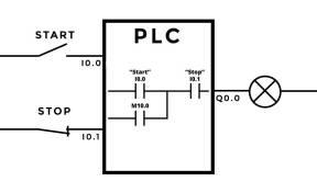
In the early days of PLCs, it was common to see the stop pushbutton wired into the PLC as a normally open contact.  This means that to stop something, the input had to be on momentarily.  It didn’t take long to figure out that if the stop input wasn’t wired up correctly, that it was not possible to stop something once you got it going.  The current practice is to wire the PLC input for a stop button as a normally closed contact (see image at left) so that the input must receive power in order to allow the output to turn on and run.  This is generally the more desirable failure scenario.  (Note that in the logic the stop is programmed as a normally open contact).

Limit Sensor Example

proxsensor1In the case of limit sensors such as mechanical limit switches, photoeyes or proximity switches to sense the end travel of a mechanism, the failure state of the devices needs to be considered.  If the mechanism fails to stop at the end limits and this can cause undesired consequences (such as equipment damage or personnel injury/death), the limit sensors are typically selected to be normally opened but held closed when the mechanism is within its operating limits.  When the mechanism is at a limit, then the sensor for that limit would no longer be held closed and the mechanism would stop (going in that direction).  When a failure occurs, such as a wire falls off, the power to the sensor fails, or the sensor fails opened, then the mechanism will stop as well.

An alternative to the above solution would be to choose a normally closed output that opens when it sensed the end of limit flag on the mechanism.  This is not as positive a solution, but sometimes it is not practical to add the necessary hardware for the limit sensors to be actuated for the entire permitted range of motion.

Solid state devices however often fail shorted (or on/closed).  What to do about that?  This also needs to be considered.

In the case where the device could fail in the “on” or “off” state a secondary method often needs to be introduced to verify (and help guarantee) that all is operating as expected.  Perhaps the most straight forward solution is to add a second sensor and some logic to detect a single failure.  If one of the sensors switches, and the other sensor does not (within a reasonable period of time), then the system would stop and an alarm would be triggered identifying the problem to the operator and/or to maintenance.

While fail-safety should always be considered to maximize reliability, it is not always necessary to do so if the consequences of failure are not serious or if the design has a certain level of inherent fail safety.  For example if the mechanism does not stop due to a sensor that has more than 1 failure state, and the worst that happens is that the mechanism runs into some mechanical stops and the drive trips out on overload without causing any damage or injury, then a single sensor may be adequate.  However even in this case, it might be worth looking for a different type of sensor that has a more well known failure state and design around that, especially if the cost is insignificant.

Often just choosing the right sensor can improve fail safety without adding cost.

Another consideration is getting the sensor to actuate reliably.  So it is important to check the installation for anything that looks marginal.  For example, with slotted adjustments I will often ask that the adjustment be pinned once everyone is satisfied with the reliability of the operation to prevent any movement of the sensor due to loosening of the adjustable settings.  Using lock washers is another option.  I’m not so trusting of slotted adjustments without pinning together (or otherwise securing) the two moving surfaces.

fail-safe-guarantee-logo

Fail Safety is NOT typically a guarantee

Fail Safe Design Limitations

Fail safe design does not mean it guarantees safety.  It may just mitigate safety.  If the simple solutions are not adequate (or seem questionable) then alternatives need to be considered to reduce the risk to acceptable levels.  This gets into more advanced subjects of performing a formalized Hazard Analysis and determining the required Safety Integrity Levels.  See references below for additional resources.

Conclusion

For this article I want to mainly point out that paying attention to the failure state of a device or system can result in no and low cost solutions that can significantly improve both the reliability and safety of a machine or process.  It can also help point to the need for a more rigorous safety review.

__________________________________

References

Fail Safe articles

https://en.wikipedia.org/wiki/Fail-safe
http://www.aiche.org/chenected/2011/02/principle-fail-safe
http://www.allaboutcircuits.com/textbook/digital/chpt-6/fail-safe-design/

Click to access failsafe.pdf

Electronics Failure Modes

https://en.wikipedia.org/wiki/Failure_of_electronic_components

Hazard Analysis

https://en.wikipedia.org/wiki/Hazard_analysis

Click to access osha3071.pdf

Safety Integrity Level (SIL)

https://en.wikipedia.org/wiki/Safety_integrity_level

https://www.google.com/url?sa=t&rct=j&q=&esrc=s&source=web&cd=10&cad=rja&uact=8&sqi=2&ved=0ahUKEwj95tiTzcbPAhVs0oMKHYuGBEsQFghQMAk&url=https%3A%2F%2Fwww.isa.org%2Fpdfs%2Fmicrosites195%2Ftr-8402p1%2F&usg=AFQjCNEWv6QF4X5vbcXXhBs-oRQwJAHqrg&sig2=NFGzk9wk5IylcLjD-nrmrg&bvm=bv.134495766,d.amc

__________________________________

Created: 10/06/2016 1:09 pm CST; Updated 10/21/2016 3:50 pm CST

for Publishing on 10/10/2016 at 6:00 am CST

Posted by: Harold Ennulat | April 13, 2015

Instrumentation & Instrumentation Engineering

Wikipedia defines Instrumentation as the art and science of measurement and/or control of process variables within a production or manufacturing area.

Instrumented Skid

Instrumented Skid

The process variables measured in industry include, Pressure, Temperature, Level, Flow, Speed, Force/Weight, Vibration, Humidity, pH, Concentrations of various gases and substances in air or liquid, or any other physical property that someone has designed a device that can measure it, including analytical devices.

Instrumentation also includes Control Valves and sometimes other types of valves such as Pressure Relief Valves.  Motors are typically not considered instruments.  Solenoids and Relays also are generally not included in the instrumentation realm.

Gauges - Click to Enlarge

Pressure Gauges

Instruments can be simple indicators and gauges with no electronics or pneumatics attached.  They include pneumatic and electronic devices and transmitters that bring the measured value (called the process variable) into the PLC, DCS, or other intelligent device that can display and/or control a process using the measured values from the instruments.

Instruments may also include panel mounted gauges, indicators, recording devices.  However these have mainly been replaced with Computer based display devices.

Loop Diagram

Loop Diagram

Signaling from an instrument is typically through a 4-20mA current loop.  The Instrument typically converts it’s internal measurement signal into a 4-20mA signal that corresponds to the measurement via a Transmitter.   For example a pressure transmitter measures a pressure say of 0 to 100 psig and transmits a signal from 4 to 20 mA (milliamps) that corresponds to the 0 – 100 psig signal where the 4 mA signal corresponds to 0 psig and the 20 mA signal corresponds to 100 psig.  A 0 mA signal indicates a broken wire or other wiring problem.  A signal between 0 and 4 mA can indicate an out of range/under-range condition and a signal of >20mA indicates an over-range condition or other failure depending on the options available for the instrument.  Loop diagrams are often created to show all of the signaling between the instrument and the PLC or DCS.

Signally between the instrument and the PLC, DCS, or intelligent device can also be done using voltage signals (such as 0-10VDC, or 1-5VDC, or even -10-10VDC for measurement of process variables that can just as likely go negative like speed), over various communications protocols such as Ethernet or wireless.

Control Valve - Click To Enlarge

Control Valve

Instrument Engineers select appropriate instruments for a given process.  Factors to consider include the desired measurement type, the measurement ranges, the process conditions that the instrument must withstand (temperature ranges, pressures, chemical resistance, environmental conditions, instrument reliability and history in prior installations under various conditions, etc.)  Working out the signaling requirements and developing loop diagrams or schematic diagrams may also fall into the instrument engineers domain.

Process And Instrumentation Diagrams (P&IDs) often form the basis for the Instrument Engineers work.  He usually assists in creating these drawings with the process engineer by adding all the instrument “bubbles”.  Once completed then all of the instruments for a project are identified.

P&ID drawing

P&ID drawing

Working on projects instrument engineers may also assemble instrumentation lists, data/specification sheets used in specifying all the requirements

Lab Setup with Various Instruments

Lab Setup with Various Instruments

of the instrument and is used to get supplier quotations and as a record of the desired and provided instrument and even to track the history of the instrument.  In this latter case the data sheet is often a report generated by a database program (such as Meridium).

Instrument Engineers may also collect data and history on instruments in their facilities, do cost benefit analysis, evaluate new instruments as they come to market, etc.  Assisting the technicians by writing calibration and other maintenance procedures and assembling troubleshooting notes and tips may also fall in the Instrument Engineers domain.

__________________________________

Created: 04/04/2015 10:00pm CST: Revised 05/02/2015

for Publishing on 04/13/2015 at 6:00 am CST

Posted by: Harold Ennulat | September 2, 2014

Sourcing and Sinking Explained

Sourcing and Sinking terminology is used when connecting solid state DC electronic devices together to make a functioning DC circuit.

As a quick reference:

– The sourcing (typically using a PNP transistor) device is connected between the positive voltage and the sinking device.
– The sinking (typically using an NPN transistor) device is connected between a sourcing device and the negative (or common) voltage.

Typical Sinking and Sourcing Digital Circuit.

A typical Sinking and Sourcing Digital Circuit using NPN transistors.

A couple of cautions:

1. Some manufacturers identify their devices as sourcing or sinking to indicate what type of device to connect to their device which can lead to some confusion.  For this reason I will ask for a drawing of the input or output circuitry of any new DC devices to make sure the two devices can be connected correctly.  The image in this post is one such example of the type of wiring diagram that might be supplied.

2. Note from the image that both the sourcing and sinking output uses an NPN (also often referred to as a sinking) transistor in this example.  This is another reason to get a drawing to make sure that current between the two (2) devices flows in the same direction. 

The above image shows the “load” as a resistive element.  However this can be a solid state device (such as a transistor that turns on when the output is “on” to turn on say a solid state relay).  In this case the current must flow in the direction of the arrows on the two (2) transistors when connected together in order to work.  This is an oversimplification as additional conditions to make a circuit also apply.  However that is the main difficulty with attempting to wire together either 2 sourcing or 2 sinking devices – you can’t get the current to flow in the same direction.

Final Note:  It is sometimes possible to connect two (2) sourcing or sinking devices together using pull up resistors.  This gets even more involved, so I’ll leave this discussion for a possible future article.

PNP Example

PNP Example

NPN Example

NPN Example

__________________________________

Reference Links:

http://instrumentationindustrialautomation.blogspot.ca/2014/08/plc-sink-and-source-io-concept.html

http://www.fluidairecompany.com/docs/pdfs/Q8answer.pdf

http://www.opto22.com/site/fd_learningsourcesinking.aspx

https://www.youtube.com/watch?v=LoBhLSpJzcY

https://www.youtube.com/watch?v=HKdJglR7NoM

__________________________________

Created: 08/27/2014 6:14 pm CST; Updated 10/21/2016 4:42 pm CST

for Publishing on 09/02/2014 at 8:00 am CST

Posted by: Harold Ennulat | April 21, 2014

PLC & HMI Tag Naming Tips

 PLC & HMI Tag Naming Tips

 And

The Impact On Rapid Code Generation

__________________________________

A Tag Naming Best Practice Suggestion

TipFor those PLC’s (programmable logic controllers or Programmable Automation Controllers) that allow the user to name each variable, I would like to suggest that as a best practice, PascalCase variable naming together with a hierarchical tag format in the form of AreaSectionEquipmentFunction be used primarily when naming variables.

So for example CheeseBelt1MotorStartPB, CheeseBelt1MotorRunCmd, CheeseBelt1MotorRunning, CheeseBelt1MotorFault, and perhaps there are 20 or 100 more CheeseBelt1.. type tags.  Here “Cheese” is the Area, Belt1 is the Section or Equipment, Motor is also a piece of Equipment (that is part of Belt1), and RunCmd is the Function.

There are many less then best examples found when doing a Google search for PLC tag naming conventions

There are many less then best examples found when doing a Google search for PLC tag naming conventions

This hierarchical form of tag naming can sometimes eliminate the need to add descriptors to the tag as the tag name is ideally self-explanatory.  This is especially true on smaller projects.  For larger projects the tags can get long and so abbreviations are often used for common names.  For example in an actual application the word for Cheese might be abbreviated “Chee” or even “C”.  In this case it might be helpful to add the word cheese to either the tag descriptor or put a list of abbreviations in a rung comment at the beginning of the program.

This hierarchical form allows for rapid code generation if say there are 2 or more Belts with the same or similar functionality.  Once the code for one Belt has been developed the code for Belt 2 is just a copy and paste of belt 1 with a search and replace of Belt1 for Belt2.  From there, Belt1 and Belt2 can be copied and pasted to make Belt3 and Belt4.  If there is a need for say 20 belts, then Belt1 through Belt9 would be copied and pasted and the word “Belt” would be searched and replaced with “Belt1” to get Belt11 – Belt19.  The more of one object that needs to be made the more efficient generating the code becomes.

This hierarchical form also allows all the variables for a particular piece of equipment to be seen by just doing an alphabetic sort of the tags.  No more hunting around to find all the variables.  Because the variables can be quickly replicated using copy, paste, and replace techniques, the tag names can stay perfectly organized.  Also if an orphan tag is generated such as CheezeBlt4…. instead of CheeseBelt4…. typos or deviations in naming become more readily apparent when browsing the tag list.

Notes on Tag Naming Standardization

I have come to prefer using the word “Run” or “Stop” to indicate a command and words ending in “ing” like “Running” or “ed” like “Stopped” to indicate status based on a PLC input. Here I used RunCmd to further clarify that this is intended to drive a PLC output.  For pushbuttons from any source including HMIs, I use the PB suffix such as StartPB, StopPB, or JogPB.  For toggles or switch inputs that are maintained, the suffixes vary somewhat but generally SW is used for ModeAutoSW or ModeManSW as functions.  (The actual mode would have the suffix of ModeAuto or ModeMan appended to the “base tag”).

Additionally most all tag names are chosen so that when the tag statement is true the tag is on or a “1” value in the PLC.  For example the RunCmd is on when the bit is a “1”, the same for “Running” or “Fault”.  The only exception might be the input for a Stop pushbutton (StopPB) as these are wired normally closed at the input of the PLC to be fail safe.  So a “0” value when the physical Stop push button is pressed will stop the device.  Often I/O are mapped to intermediate tags and in these cases the input is inverted again as it is brought into the logic so that the StopPB again will turn to a “1” when the device is to stop.  Analysis shows that this can be done without losing any fail safety, though it often isn’t immediately obvious for programmers new to this idea.

There can be many more rules applied on any particular project but the above two (2) points have been common for most all my projects where I got to decide. For larger projects it is not uncommon to start and maintain a tag dictionary for how names are constructed, a list of abbreviations and the meaning of abbreviations.  This is especially useful when 2 or more people are writing code, but can be useful for even one engineer that might need to take a break from the program.

Tagging Using Structured Tags

For PLC’s that support structured tags (also called user defined tags) the tags in the above example could also be structured as CheeseBelt1.Motor.RunCmd, CheeseBelt1.Motor.Running, CheeseBelt1.Motor.Fault, etc.  With structured tags there may only be one tag that encapsulates all the elemental tags associated with Belt1.  Therefore making a Belt2 tag is just a matter of making another instance of the structured tag that was used for Belt1.  When an element needs to be be added for Belt1 through Belt5 for example, then only the definition of the structure needs to be changed for all 5 belts to get the new elemental tag.

Structured Tag use in User Defined Instructions

Structured tags are even more powerful when they are combined with User Defined Instructions (Called AOI’s by Rockwell, DFBs by Schneider, and Blocks such as FCs by Siemens).  A CheeseBelt1 control could be contained in a single User Defined Instruction with just one structured variable called CheeseBelt1.  Making additional CheeseBelts would require just inserting a single instruction block and assigning a single structured tag for each additional belt.

This can greatly improve program development time and program maintainability.

The primary caution to using structured tags or user defined instructions/blocks is that they are not always editable when online with a running processor.  So choosing which of the above methods to use is often influenced by what kind of changes might be needed in the field to the running machine.

Another caution is that if there is a lot of debug or maintenance required, the process can be more tedious if you only have a few instances of the instruction in the program.

__________________________________

When Not To Use Hierarchical Formatted Tags

There are times however when it seems prudent to deviate from the hierarchical AreaSectionEquipmentFunction approach.  An example of this is when there is a need to write code that needs to index through an array.  In this case the variables may be defined as array elements.  However depending on the manipulation that is needed, the array elements may be structured tags.  This will allow for some level of clarity in the meaning of the tags.

Array tags generally require additional documentation to clarify the meaning of each tag element so array tag use should be limited only if special manipulation is needed that requires an index to search or loop through the array.

__________________________________

Wish List

WishListI am looking for a time when PLC software will allow some kind of enumeration capabilities in the named tags, so that arrays with numeric index numbers can be eliminated, but as of this writing I am not aware that this kind of functionality is available from any of the major PLC manufacturers.

__________________________________

Created: 04/16/2014 6:14pm CST; Edited 04/21/2014 3:44pm CST:

for Publishing on 04/21/2014 at 7:55 am CST

Posted by: Harold Ennulat | March 3, 2014

TheCaseForCamelCase – Or is it PascalCase?

CamelCaseHere are some links that help make the case (or for many, help reinforce the case) for CamelCase notation in the naming of variables in any kind of programming including PLC and HMI development work.

http://en.wikipedia.org/wiki/CamelCase has interesting comments about the readability of Camel Case which apparently is a common criticism.

http://en.wikipedia.org/wiki/Naming_convention_(programming).  A general description of variable naming conventions.

http://msdn.microsoft.com/en-us/library/x2dbyw72(v=vs.71).aspx suggests that CamelCase is more accurately called PascalCase since technically CamelCase should really be camelCase to be camel case….

http://cplus.about.com/od/learnc/ss/csharpclasses_5.htm  cites the Microsoft Design Guide as also distinguishing the use of camelCase from PascalCase.

http://cplus.about.com/gi/o.htm?zi=1/XJ&zTi=1&sdn=cplus&cdn=compute&tm=69&f=00&su=p284.13.342.ip_p504.6.342.ip_&tt=29&bt=5&bts=5&zu=http%3A//msdn2.microsoft.com/en-us/library/czefa0ke%28VS.71%29.aspx.  Microsoft .Net Design Guidelines suggests usage for both camelCase and PascalCase naming of variables, and structures.

For this author, I’m not as concerned about what it is called, but that this variable structure be considered as a best practice when naming variables in PLC or HMI applications.  However I learned that what I prefer to use is actually called PascalCase.  In the circles I’ve traveled we’ve called it CamelCase for so long that I’m going to have to adjust my vocabulary, even though some of the sources cited above don’t necessarily make this distinction.  But then who can argue with Microsoft?

In a future post I’d like to discuss how to structure the naming of variables in a hierarchal format in the form of AreaSectionEquipmentFunction when naming variables and also review the benefits of this method in rapid code generation.

________________________________________________________________________

 Created 3/2/2014 4:00 pm | Published 3/3/2014 5:00 am

Posted by: Harold Ennulat | January 13, 2014

2013 in review

According to WordPress, this blog was viewed about 14,000 times in 2013. That’s another record year, with readership doubling over the last 2 years.  Your views, readership and comments are most encouraging.

Click here to see the complete report.

Posted by: Harold Ennulat | November 12, 2013

Advanced PID Control Example: Hot Water Temperature Control

HW08HeaterAsOrdered-1024x625What follows is a very instructive article on a PID temperature loop control example by Wayne Salo over at Excel Engineering in the St. Paul, MN area.  It shows how temperature control can start as a fairly simple system,

Final Solution

Final Solution

but over time (and as learning takes place) the control can get fairly complex as the desire for tighter control increases as was the case in this project.

The project was posted as 4 separate Blog articles over a period of time starting with http://74.95.67.199/controls/2013/03/18/hot-water-project-phase-1/.  I’m republishing these articles here so the reader can see the progression of solutions offered, all to achieve increasing levels of control needed for what turned out to be a tightly controlled application using process knowledge, feed forward, and a cascaded PID control.

_______________________________________________________________

Hot water project – Phase 1

Posted on March 18, 2013 by 

One of the more common projects is to heat water (or some other liquid) from a random cold temperature to a desired working temperature. The inevitable discussion occurs with your boss or the customer regarding the usual items – schedule, scope and costs.

If you are lucky, the customer has properly identified the scope of the project. He has adequately determined the variation of the process input temperatures and flow, variations in the heating media, identified the economic value of maintaining a specific temperature or incremental losses due to off-spec temperatures and identified potential future uses and changes for the output of this process. He would also have properly identified reasonable capital costs and provided adequate lead time for this engineering process.

Dream on! The majority of projects seem to be “We are tight on the schedule, we needed the control design done yesterday”. “Oh, by the way, this was an oversight so we don’t have any budget identified for the control equipment, so the cheaper the better”. “You may want to talk with the Project Scheduler so we can keep your costs in tow”. “All of the information you need is in the plant documentation files”. “The Process Engineer has already bought all of the control elements so you may want to talk with him”.

In subsequent discussions with the Project Manager and Process Engineer you find that a closed tube and shell heater (a heater in which the heating and process fluids do not mix) has been ordered. The heating media will be steam and condensate drips will be removed from the shell by pump. The process fluid is water and the final users/process will control the water throughput. The heating steam admission valve and process water flow valve have been procured. Both valves were purchased with trim linearized within the process piping. The downstream process that uses the heated water is proprietary and if they tell us about the process they will likely have to shoot us.

HW08HeaterAsOrdered-1024x625

The system as ordered appears relatively simple. Following the instructions as requested by the customer, a simple (cheap) control system was created. HW09HeaterAsOrderedControl1-224x300The temperature of the water exiting the heater was measured, compared with an Operator adjustable setpoint and the Heater Steam Supply Valve is manipulated to control the water outlet temperature.

The system is commissioned and tuned and it appears the customer is initially satisfied that the control system is working as requested. All is good and it is time for a beer.

Six months later the customer calls and is now unhappy with the system performance. They have performed testing and some areas of opportunities were identified.

Next time – Hot water project – Phase 2

Hot water project – Phase 2

Posted on April 11, 2013 by 

As we noted in the last blog, the customer has told you he is unhappy with the temperature control of the process water. After signing a telephone book of nondisclosure agreements the customer has offered additional information regarding his process.

During the past months of operation they have been able to characterize the efficiency of the process in which the steam is being used. They inform you that the water is being used to supply a bioreactor with process water. In addition they have provided you with charts that indicate the process efficiency versus the water temperature presented to the bioreactors and Piping and Instrumentation Diagrams (P&ID).

HW10EnzymeEff1

We also note that the customer has identified that the best operating point is at 112 degF and the production efficiency falls off significantly both above and below this target temperature. The enzyme reactants are expensive and it is in their interest to minimize the waste and costs by more accurately controlling the temperature.

HW11HeaterBioTrain13

Also it was noted that the usage by the reactors was inconsistent and changes in the flows were causing a sluggish response in the final temperature. When one of the reactor trains is placed into service or removed in service, the flows would dramatically change and the spikes in temperature would waste reactants. They needed a mechanism to properly respond to these changes in demand. They also remind us that their operational budget does not necessarily have lots of money available for any changes – so the cheaper the better. So we decided to track the position of V2 (the water flow control valve) and feed forward that signal to the steam valve V1 to minimize anticipate the demands for the steam heating requirements. As a result the following control scheme was provided.

HW12Heater2ndTry12

Since the process engineer had linearized the valves we could easily relate the water flow valve position to an appropriate position demand for the steam supply valve. The system was configured, scaled and tuned, the customer is happy with the change – time for another beer.

We receive a phone call approximately 3 months later and the customer informs us that the control performs better – but – there is a problem when the water inlet pressure to the heater changes and the water valve position does not accurately represent the flow through the system.

They ask for a change to correct the problem.

The next step in the process –
Next time – Hot water project – Phase 3

Hot water project – Phase 3

Posted on May 4, 2013 by 

As we noted in the last blog, the customer noted that the water pressure varied and the water control valve position did not necessarily represent the flow through the heater. The customer has indicated that they would be able to release some additional funds for process instrumentation.

At this time a flow measurement of the incoming water was added and the control configuration modified and rescaled to respond to actual water flow.

HW14HeaterFTFeedForward14

A flow transmitter, FT2, was added and used to replace the valve position feed forward. Since we know the relationship between flow and heating demand we were able to easily rescale the feed forward to steam valve position demand change.

Modifications were made to the configuration, blocks rescaled and system retuned. Customer exercised changes in the upstream water pressure and was again happy with the new configuration results.

Again we received another phone call approximately 3 months later. The customer indicates that when they switch from city water at 70 degrees to well water at 50 degrees, the system takes too long to respond to these changes. They asked if we could help them with the response of the system.

At this time we proposed that we actually measure the incoming water temperature and anticipate the demand to the steam valve. After the customer agrees to the additional costs of the instrumentation, we provide a new solution.

HWHeaterSteamFTFeedForward16

With this modification we no longer depend on the design differential temperature demand for the feed forward, we actually measure the flow and needed increase in water temperature. From these we can directly calculate the power demand and feed forward this scaled demand to the steam valve. Again the system is reconfigured, rescaled and tuned. And again the customer is happy with the changes made to the system. And again we are ready for beer time.

The customer calls back approximately 3 months later and indicates that there are still opportunities to minimize temperature deviations. They have noted that when the other process steam demand changes, the inlet steam pressure changes and they do not necessarily get the steam flow desired into the heater.

Next time – let’s get the steam under control.
Hot water project – Phase 4

Hot water project – Phase 4

Posted on June 10, 2013 by 

As we noted in the last blog, the customer noted that the steam pressure varied and the steam control valve position did not necessarily represent the steam flow to the heater. Let’s get the steam under control.

We tell the customer that the addition of instrumentation to the steam lines will cost more than the previous instruments we have already added. They indicate that even small reductions in the loss of reactants would cover any of the costs of new instrumentation.

We inform the customer that we will add a temperature compensated steam flow meter and reconfigure the controls to accommodate the new instrumentation. The following is the new control arrangement.

HWHeaterSteamFTFeedForward16

You will note that we have now moved from a simple feed forward control to a feed forward – cascade control system. The reason for the cascade is we now are actually controlling the steam flow by manipulating the steam valve. The “inner loop” (steam flow) will be tuned first and then the “outer loop” (steam flow demand) will be tuned. The feed forward is now rescaled from valve position to steam flow demand. And again we implement and tune the new configuration. The customer is happy with the new and smaller error band of the water temperature.

The customer calls again in several months and indicates that they have related some small temperature differences in the water to incoming steam temperature. Reducing these temperatures could again reduce the loss of reagent in the bioreactors. We have one final change and inform the customer that it will not require the addition of any instrumentation – only some engineering and reconfiguration of the control arrangement. The following is what was proposed.

HWHeaterSteamHFeedForward17

In this case we add an enthalpy calculation to the steam. Some manufacturers have this block built-in to their algorithm set but in most cases this calculation is performed using multiple blocks. Using the steam pressure and temperature we can calculate the energy contained within the steam (enthalpy). Since we also are measuring the actual steam flow, we can now directly control the energy entering the heater due to the steam. This is a full model of the process. We measure and calculate the energy demand required by the water and directly control the heating energy provided by the steam.

The control configuration is rescaled such the inner loop controls the total BTU/Hr provided by the steam while the feed forward and outer loop is rescaled to BTU/Hr.

The result of this set of blogs on the heater project is a take-away with several lessons.

  • .   – Many of the control projects begin as an afterthought.

o Budgeting, scope and schedule need proper attention
o Major needs are not included in base design
o Operational efficiencies may not be appreciated

  • .  – Skill set of the Process Engineer may not include adequate control skills

o The Process Engineer may understand process very well but not all of the associated interactions needed for the application and design of the needed control arrangement

  • .  – Management and operations live with the limitations of the control process. They do not want to spend the money or shut down production for any enhancements. The revenue they may lose due to the maintenance shutdown is a deterrent to any appropriate upgrades to the system.

o Most control projects do not evolve beyond first simple regulatory control implementation (Process Measurement -> PID controller -> Manipulated device).
o Extensive efforts are made to adapt and modify the tuning parameters with respect to the existing measured parameters but no additional efforts are made to add instrumentation and properly enhance the model of the application.

  • .  – Spending the time and effort at the beginning of the project to determine scope of instrumentation and control required for the long-term best profit over the life of the system will pay off large in the long run. Establishing a proper design and cash-flow will identify the extent of modeling that will be cost effective.

_______________________________________________________________

 For Waynes other articles on Process Control see http://74.95.67.199/controls/.

_______________________________________________________________

|  Created: 11/1/2013 10:55 am CST; for Publishing on 11/12/2013 at 5:00 am CST

Posted by: Harold Ennulat | November 4, 2013

Thunderbolt To Replace USB & Firewire?

ThurderboltCable296113We are starting to see computers and peripherals coming out with the Thunderbolt interface included.  This interface supports data rates up to 20 gigabits per second.  Impressive speed!

The connector is a Mini DisplayPort connector and so is sized to fit in portable devices.

It looks like the price point is in line with USB solutions.  This raises the question “Will Thunderbolt replace USB, Firewire and eSATA?”  While these interfaces will likely co-exist for years to come, Thunderbolt seems poised to dominate, especially with so many manufacturers now offering this interface in their products.

See Below or click to enlarge

See Below or click to enlarge

This interface handles both data and video content and can route data or video streams directly to the proper hardware channels.  This means that you can hook a compatible monitor directly to this port, or you can connect a compatible hard drive for data connections to this same port.  It will be interesting to see if interface devices start to show up that convert signals from one interface type to another, so that a smart phone with a USB connection can be plugged in a computers Thunderbolt port.  This won’t be something that will be needed soon for USB devices, as the new line of computers still have USB ports as well.  However the option for eSATA and FireWire ports might diminish fairly quickly, especially if converters do become readily available for these more specialized needs.

It would seem prudent to be looking for this interface in your next PC, laptop, or high-end tablet device.

________________________________________________________________

Here is a collection of images that describe the interface in some detail.

________________________________________________________________

Performance Comparison with USB, Firewire, and eSATA:

ThunderboltInterfaceComparisonChart-5147864-11387664

________________________________________________________________

A Conceptual View:

ThunderboltHowItWorks-600

________________________________________________________________

The Architecture:

ThunderboltArchitecture

Click on images to enlarge

________________________________________________________________

Connector Details:

ThunderboltConnectorAndCable_Page_06

________________________________________________________________

For additional details see the Wikipedia article on Thunderbolt.  This article provides additional specifications, details on the pin outs, and the history of this interface.

________________________________________________________________

|  Created: 10/30/2013 1:14pm CST; Edited 10/30/2013 2:29pm CST:

for Publishing on 11/4/2013 at 5:00 am CST

Posted by: Harold Ennulat | July 1, 2013

Control Panel SCCR Rating Requirements

Control Panels do not necessarily require SCCR (Short Circuit Current Rating) labeling.

Click to enlarge to see Fault Current (i.e. SCCR) labeling info.

Click to enlarge to see Fault Current (i.e. SCCR) labeling info.

The 2011 NEC (National Electrical Code) book, section 409.110 (4) confirms that Industrial Control Panels require SCCR labeling.  However, the 2011 NEC has an exception noted stating “Short-circuit current rating markings are not required for industrial control panels containing only control circuit components”.

In comparing this with the 2005 NEC Handbook, this exception did not appear in this version of the NEC code. 

So now the question is how do you rate a panel with a 480VAC 100KA SCCR rated power circuit with control circuit components that are unrated or have only a 5KA SCCR ratings.  It would seem that the panel would in this case need to be rated at 5KA SCCR.

So at this point it seems that we may need to split our Control Panels into “..panels containing only control circuit components” and power panels with a suitable SCCR rating.  This has been my preferred practice ever since I was restricted in servicing some 24VDC circuit because the panel also contained 480VAC motor controls.

For more of my thought on this subject see “Designing for Electrical Shock and Arc Flash Safety“.

________________________________________________________________

My Thanks to Dave Wood at Control Assemblies in Plymouth Minnesota for pointing this out to me and forcing me to examine this for myself.

________________________________________________________________

 |  Created: 6/20/2013 3:30pm CST; for Publishing on 7/1/2013 at 5:00 am CST

Posted by: Harold Ennulat | June 24, 2013

Grain Handling Fire & Explosion Hazards For Control Engineers

Grain Handling Fire & Explosion Hazards

Review For Controls Engineers

___________________________________________________

As I find myself doing more grain elevator controls and working on adding sensors to notify the operators and shutdown equipment in order to avoid potentially hazardous situations, I thought it good to research and review the regulations and concerns surrounding grain elevator fire and explosion hazards.  References are noted at the end of this article.

GrainElevatorFireshib073105_02Grain elevator fires and explosions are fairly well documented.

Dust explosions require 5 elements to exist simultaneously to trigger a fire and/or explosion.  These are:

Elements Needed for a Fire (the familiar “Fire Triangle”):

1.   Combustible dust (fuel);
2.   Ignition source (heat); and,
3.   Oxygen in air (oxidizer).

Additional Elements Needed for a Combustible Dust Explosion:

4.  Dispersion of dust particles in sufficient quantity and concentration; and,
5.  Confinement of the dust cloud.

“OSHA 29 CFR 1910.272 simply titled “Grain Handling Facilities” is the primary document regulating practices in these types of facilities.

The primary controls and sensors that are being added to reduce the risk of explosions and fires are:

1.  Key bearing temperature monitoring

This is noted in OSHA Standard 29 CFR 1910.272 (q)(4)(ii) where it states: “Provide vibration monitoring, temperature monitoring, or other means to monitor the condition of those bearings mounted inside or partially inside the leg casing”.

2.  Belt alignment sensors ( or belt rub blocks with temperature monitoring)

This is noted in OSHA Standard 29 CFR 1910.272 (q)(6)(i) where it states: “The employer shall: Equip bucket elevators with a belt alignment monitoring device which will initiate an alarm to employees when the belt is not tracking properly; or, Provide a means to keep the belt tracking properly, such as a system that provides constant alignment adjustment of belts”.

3.  Conveyor slow down sensors.

This is noted in OSHA Standard 29 CFR 1910.272 (q)(5) where it states: “The employer shall equip bucket elevators with a motion detection device which will shut-down the bucket elevator when the belt speed is reduced by no more than 20% of the normal operating speed”.

Section (q) applies to “Inside bucket elevators” which are defined as …a bucket elevator that has the boot and more than 20 percent of the total leg height (above grade or ground level) inside the grain elevator structure. Bucket elevators with leg casings that are inside (and pass through the roofs) of rail or truck dump sheds with the remainder of the leg outside of the grain elevator structure, are not considered inside bucket elevators”.

Another point worth noting is that OSHA (in section (q)(4) does not require bearing temperature monitoring if the bearing is not mounted “inside the leg casing”.  All of the bucket and belt conveyors I’ve worked with had the bearings outside of the conveyor casing or enclosure and yet they have bearing sensors installed in them.  As for vibration monitoring in lieu of temperature monitoring, this is something I’ve not seen or heard about as something implemented.  The reason is likely that temperature monitoring is probably more straight forward.

Many in the industry believe that OSHA will be strengthening these requirements to automatically shut down equipment not only if the speed of the bucket elevator slows down, but also if the bearing temperatures get to high or the belt goes out of alignment.  Additionally these rules are also being applied to any type of belt conveyor.  For drag conveyors only bearing temperatures are generally monitored.  Alignment sensors and the slow down sensor are not seen as needed for drag conveyors since these are driven by a sprocket guided chain and have sensors to detect a chain break condition.

I was unable to find any information supporting the belief that OSHA will strengthen the existing requirements.  I would invite the reader to comment with additional insight on this topic.

___________________________________________________

When considering the risk or fire or explosion, a big concern is secondary explosions that are caused by the dispersal of grain dust into the air from the first explosion that in many cases is more severe than the initial explosion.

DustSecondaryExplosionIllustrationshib073105_04___________________________________________________

REFERENCES:

1. OSHA Standard 29 CFR 1910.272 (q)(4)(ii), (q)(5), (q)(6)

2. Regulatory Review Of OSHA’s Grain Handling Facilities Standard [29 CFR 1910.272] http://www.osha.gov/dea/lookback/grainhandlingfinalreport.html

3. Grain Handling: http://www.osha.gov/SLTC/grainhandling/standards.html

4. Combustible Dust in Industry: Preventing and Mitigating the Effects of Fire and Explosions http://www.osha.gov/dts/shib/shib073105.html

5. NFPA 654, Standard for the Prevention of Fire and Dust Explosions from the Manufacturing, Processing, and Handling of Combustible Particulate Solids

6. NFPA 61, Standard for the Prevention of Fires and Dust Explosions in Agricultural and Food Processing Facilities.

___________________________________________________

 |  Created: 6/22/2013 5:30pm CST; for Publishing on 6/24/2013 at 5:00 am CST

Older Posts »

Categories